
Yes—for isolated functions and well-defined requirements. The more interesting question is what it takes to turn that capability into useful automation software for a complete machine.
Industrial engineering platforms are already moving in this direction. CODESYS describes AI-assisted engineering that can create PLC program blocks, work with existing project code and use compiler and error-checking tools through its Development System MCP Server.
These capabilities make code generation a practical topic. They do not, by themselves, establish that the generated software implements the intended machine behaviour.
Can AI understand a machine well enough to generate the correct PLC software for it? That is the engineering question behind the code.
A functional specification is not a PLC program.
Imagine a relatively simple requirement:
AI can draft Structured Text for that sequence. An automation engineer immediately sees the decisions that still need to be defined:
- What happens if the cylinder never reaches the work position, and what timeout applies?
- Under which guard-door and safety conditions is movement permitted?
- Which operating modes allow movement, including manual commands?
- What happens after an emergency stop, and which conditions govern any restart or resumption?
- What diagnostics must appear on the HMI?
- Which valve technology is used?
- Are both Home and Work sensors present, and what should conflicting sensor states mean?
- How are the signals mapped to the PLC?
- Which customer programming standard must be respected?
A detailed functional specification may already answer many of these questions. A short description of the nominal cycle does not. The software must implement the required behaviour across relevant operating and fault conditions.
Resolving the remaining gaps is engineering work. Safety-related functions also require the machine-specific safety architecture and validation process; they cannot be inferred as ordinary sequence logic from a prompt.
PLC code is the result of many engineering layers.
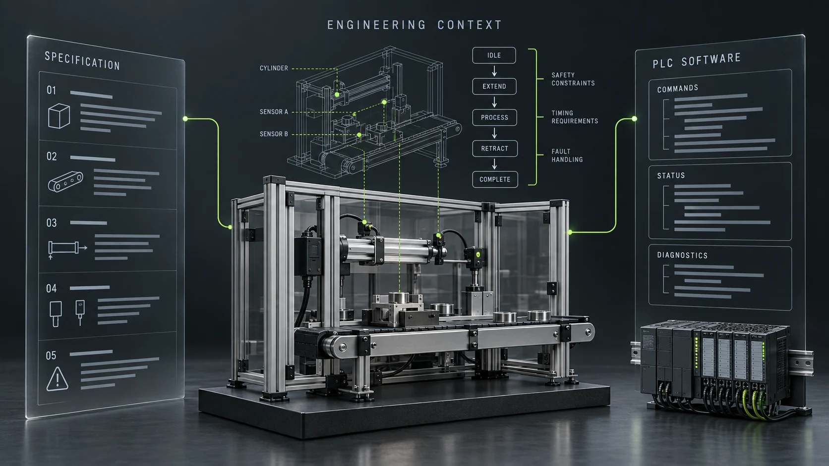
A machine program is rarely created from one document. An automation engineer combines information from mechanical design, electrical schematics, I/O lists, pneumatic diagrams, safety architecture, robot interfaces and drive configurations.
Customer programming standards, functional analysis, commissioning feedback and previous machine projects add further context.
The resulting PLC program implements that engineering context.
A language model may interpret the sentence “Move Cylinder 12 to Work Position”. The engineering system needs to establish what Cylinder 12 actually is: a double-acting pneumatic cylinder, controlled by a particular valve, monitored by two sensors, connected to specific I/O channels and belonging to Station 40.
It also needs the movement permissions, diagnostic requirements and naming conventions that apply to that equipment. This information provides a basis for generating software that can then be checked against the intended behaviour.
The challenge goes beyond syntax.
IEC 61131-3:2025, in the preview hosted by PLCopen, specifies Structured Text, Ladder Diagram and Function Block Diagram, along with Sequential Function Chart elements for organising programs and function blocks.
Producing plausible code in a defined language is one task. Constructing the engineering model behind it is another.
Consider what an automation engineer associates with a double-acting cylinder:
- Physical layer
- Cylinder, valve, Home sensor and Work sensor.
- Electrical layer
- Valve control outputs and sensor inputs, mapped to the relevant channels.
- Control layer
- Cylinder function block, commands, status, timeout supervision and interlocks.
- Sequence layer
- Move Home, wait for Home, move Work and wait for Work, within the specified sequence.
- HMI layer
- Position display, permitted manual commands and diagnostic information.
- Alarm layer
- Home-position timeout, Work-position timeout and conflicting sensor status.
The word “cylinder” represents an engineering object with relationships and behaviour. Industrial knowledge is what connects these layers.
Compiling successfully does not mean the machine will work.
Generated code can be checked with the target compiler. That is useful, but insufficient.
A program can compile and still command the wrong actuator, create an impossible sequence, ignore a mechanical constraint, mishandle fault recovery, violate a customer convention or provide poor diagnostics.
The software eventually controls physical equipment. An incorrect assumption about recovery after an interrupted cycle may become visible only when that situation is tested, potentially during commissioning.
Validation therefore needs to ask more than whether the code compiles:
Does the resulting machine behaviour correspond to the engineering intent?
A hybrid architecture could make the context explicit.
A promising direction is an intermediate engineering representation between the functional specification and the generated software.
For example, a workflow could build up four connected stages:
Functional specification
Capture requirements and identify missing or contradictory information.
Machine understanding
Represent stations, equipment, actuators, sensors, operations, states, interlocks, safety constraints and interfaces.
Engineering rules
Apply customer standards, naming conventions, reusable objects, hardware rules, diagnostic principles and sequence patterns.
Software generation
Produce or populate PLC software, HMI elements, I/O configuration, alarms, robot interfaces, documentation and tests for review.
In this proposed architecture, AI helps interpret and classify information, connect requirements and surface unresolved questions. Missing engineering decisions remain visible for resolution.
Deterministic rules and reviewed templates govern repeatable transformations. Their correctness still needs to be established. Engineers validate the intended behaviour and review and test the resulting implementation.
From an AI coding assistant to an engineering system.
Coding assistants can help with functions, legacy-code explanations, Structured Text drafts and programming errors. Those are useful contributions.
The broader opportunity is to support the engineering reasoning that connects the mechanical design, electrical architecture, PLC software, HMI, robot programs and functional specification.
If those relationships can be represented explicitly, PLC code becomes one of several possible outputs. The same approved knowledge could also inform electrical engineering elements, HMI objects, alarm definitions, robot interfaces, test procedures and commissioning documentation.
The industrial knowledge model behind the generator becomes a central asset.
So, can AI generate PLC code from a functional specification?
Yes, within a defined scope. Generating production-ready software for a complete industrial machine requires the engineering context, review and validation behind that code.
The real challenge is reconstructing the reasoning normally performed by an automation engineer: what equipment exists, how it is connected, how it should behave, under which conditions and according to which standards.
It must also address what happens when reality does not follow the nominal sequence.
The future may be about teaching AI how engineers understand machines.
Bring industrial context into your AI workflow.
FACTREN helps technology builders understand real industrial engineering environments and helps industrial companies evaluate emerging AI against their engineering workflows.
Discuss your industrial AI projectSources & scope
CODESYS’s product documentation describes its own capabilities; this article is not a FACTREN product test or endorsement. The IEC reference is to the 2025 edition. Sources checked on 21 September 2026. The cylinder example and proposed architecture express an engineering perspective, not a validated machine design or an available FACTREN software product.